October 19, 2012

RIP Version 2 on Packet Tracer

There is no big difference between RIP version 1 and version 2 when we are applying them in packet tracer. In order to apply RIP version 2 on packet tracer. we will just have to add the following command. We will follow the same example that we used in RIP version 1 in this article.

rip

Router(config)# router rip
Router(config-router)# network 192.168.1.0
Router(config-router)# network 192.168.2.0
Router(config-router)# version 2
Router(config-router)#exit

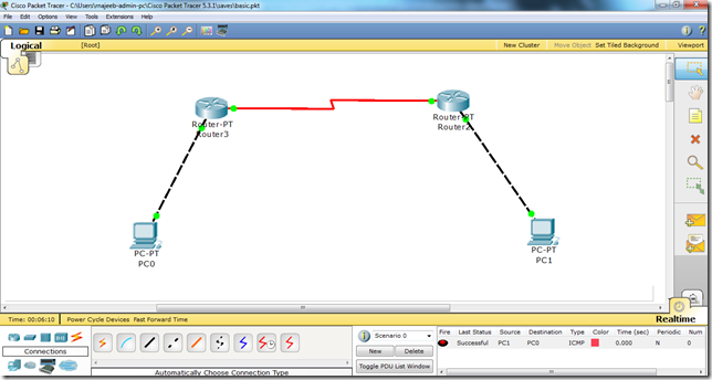
You see there is just the addition of one statement i.e. “version 2”. The rest is the same. We will apply the above set of commands on both routers i.e. Router 3 and Router 2 ,used in the topology above which is also used in this article, above and bingo, we have applied RIP V2 on packet tracer.
Just make sure that the protocol is applied as an additional step and cannot replace the basic steps i.e. we have to assign IP addresses to the router’s interfaces and PCs and also change the state of the interfaces from down to UP like in this article and then we will go ahead and apply Protocol.


RIP on Packet Tracer

Main Commands
clip_image002
You need to advertise only the classful network number, not a subnet.
Explanation:
Lets apply RIP protocol on the following topology.


Now, we will follow the steps as mentioned in detail in the following article. i.e.
i. We will assign IP addresses to all the fast Ethernet and serial interfaces respectively.
ii We will change the state of the interfaces from down to UP.
Then, after we are done with the basic step. We will apply RIP protocol commands on both routers.

Configuration of Router 0 i.e. configuring both serial and fastethernet interfaces.


Configurations of R1


Assigning IP address to PC0


Assigning IP address to PC1


R1
In order to apply protocol RIP, we will write the following set of commands.

Router(config)# router rip
Router(config-router)# network 192.168.1.0
Router(config-router)# network 192.168.2.0
Router(config-router)# network 192.168.3.0
Router(config-router)#exit


R2:
In order to apply protocol RIP, we will write the following set of commands on R2 as well.

Router(config)# router rip
Router(config-router)# network 192.168.1.0
Router(config-router)# network 192.168.2.0
Router(config-router)# network 192.168.3.0
Router(config-router)#exit


Write all the commands in the same fashion as in the above screen shots and voila, we are done with RIP protocol. Another important thing here is that we will add all the networks that we are using in our topology. Here in this particular example i am just using two networks x.x.1.0 and x.x.2.0 so thats why i have added these two network addresses to the RIP protocol.

Now, you can check it. Traffic is enabled and you can easily send data from PC0 to PC1.


What is Packet Tracer

Packet Tracer is a powerful network simulator that can be utilized in training for CCNA and CCNP certification exam by allowing students to create networks with an almost unlimited number of devices and to experience troubleshooting without having to buy real Cisco routers or switches. The tool is created by Cisco Systems. The purpose of Packet Tracer is to offer students a tool to learn the principles of networking as well as develop Cisco technology specific skills. However, it is not be used as a replacement for Routers or Switches. 

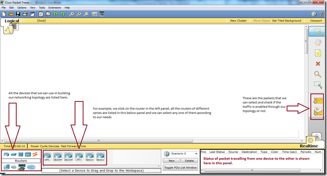
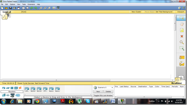
Here how it looks like after we start it.

ptfirst

We are different modules and panels available in the packet tracer. Some important modules, which are important to understand for the working in Packet Tracer, are mentioned in the following diagram.

pt

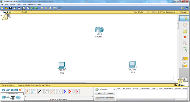
Now, in order to create a topology, we will have to select some of the devices and put them in our main window i.e. the white portion of packet tracer. and here how it looks after we add the devices.

1

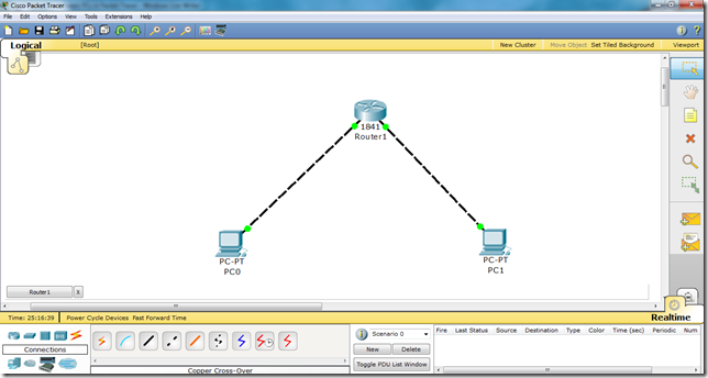
Now, we will have to connect these devices and for that we use cables. To understand the cables, please refer to my following article.

new

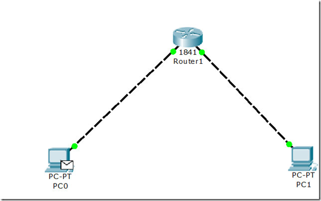
And after you successfully create the topology, you can check either the traffic is flowing or not by selecting the packet from right panel and putting it on both PCs as follows.

2pac

For detailed article on making the topology and successfully enabling the communication, read this article


Technorati Tags: What is packet tracer, pt activities,  how to work on packet tracer,  packet tracer tutorial, how packet tracer works,  packet tracer topology,  packet tracer networking,  networking in packet tracer

October 17, 2012

Communication between PCs in Packet Tracer

Here, we will see communication enabled between PCs via Router in Packet Tracer.
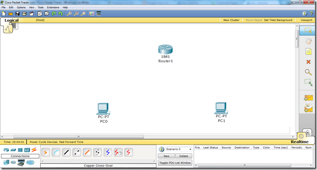
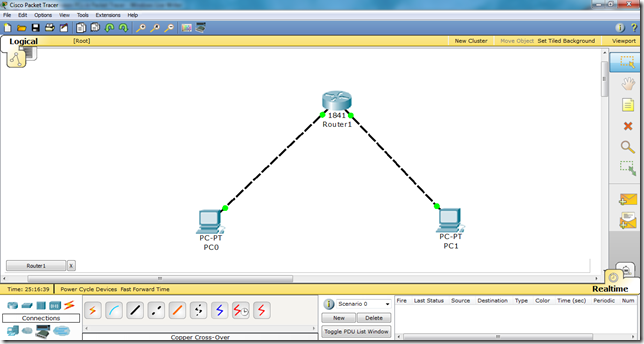
So, for this we need two PCs, a router ,and two cross over cables to connect them.
Important point is that we use cross over cable to connect PC to a router because they both use the same pins for transmission and receiving of data.

1

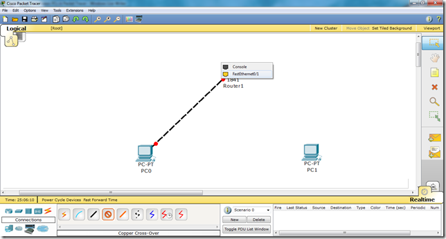
Now, we will connect them by selecting fast ethenet interfaces on both ends.
2
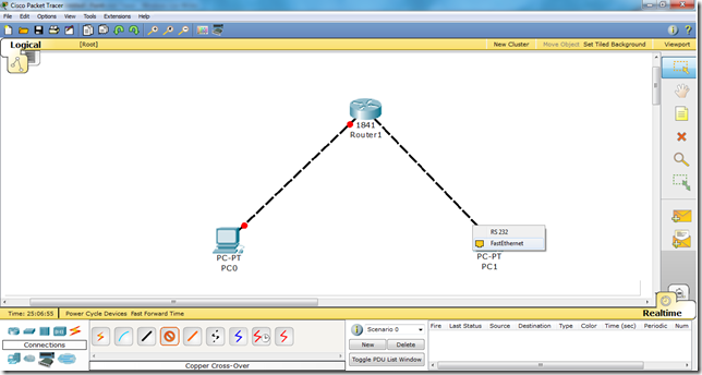
Similarly, on the PC side we will select fast Ethernet interface.
3
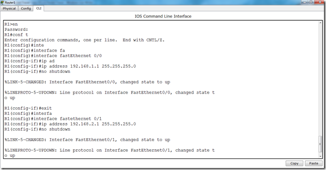
Now, we have connect the devices. Further, we will go to the router CLI mode and enter the following commands.
Step by step ,
we will have to do the following things.
i. Access the interfaces one by one
ii. Assign IP addresses to interfaces
iii. Change the status of the interfaces i.e. from Down to Up.
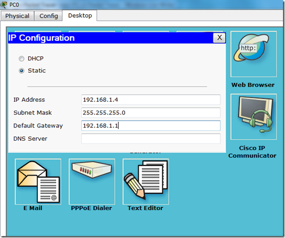
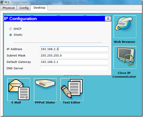
iv. Assign IP addresses to PCs.
v. Assign Default GateWay to PCs. FYI fast ethernet ip address is the gateway address to the PC. 
Now, commands of the Router CLI mode are as follows.
int
Now, we have accessed both interfaces one by one and we have assigned IP addresses respectively.
new
See the difference the lights have changed the color from Red to Green :)
Now, lets assign IP addresses to the PCs.
Click on PC1, go to Desktop, then click IP Configuration.
PC1:
pc1
PC2:
pc2
Now, our communication is enabled and we are able to communicate from PC1 to PC2 via Router.
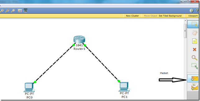
Click on the packet in the right panel on the packet tracer, then click on PC1 and then click on PC2. You will see the successful packet tracer (status is shown in the bottom right corner)
packet
Select it and click on both PCs.
2pac

Bingo, your communication is successful.

Packet Tracer CLI

There are various common commands that one needs to be familiar with. These commands will be used all the time.

There are different modes. All modes have their own distinct commands.

clip_image002


All the configuration commands will be written in configuration mode.

Using the tab Key to Complete Commands

When you are entering a command, you can use the tab key to complete the command. Enter the first few characters of a command and press the tab key. If the characters are unique to the command, the rest of the command is entered in for you. This is helpful if you are unsure about the spelling of a command. For example, if we write in enable mode, “sh” and press tab button, “show” command will be written on the CLI mode.

clip_image002[6]

Router Modes

clip_image002[16]

clip_image004

TIP: There are other modes than these. Not all commands work in all modes. Be

careful. If you type in a command that you know is correct—show running-config, for example—and you get an error, make sure that you are in the correct mode.

Entering Global Configuration Mode

clip_image006

Configuring a Router Name

This command works on both routers and switches.

clip_image002[18]

Configuring Passwords

These commands work on both routers and switches.

clip_image004[5]

Here it is important to know that the enable secret password is encrypted by default. The enable password is not. For this reason, recommended practice is that you never use the enable password command. Use only the enable secret password command in a router or switch configuration. You cannot set both enable secret password and enable password to the same password. By doing so, it defeats the use of encryption.

Show Commands:

There are various show commands. in order to get familiar with these commands just write “show ?” in the enable mode.

show

Similarly, there are various commands that shows us the configurations that we have done on our router or any other device depending on the device we are working on. We will talk about later on.

Similarly, there are various commands in the configuration mode which we attain by entering the following command

Router# configure terminal.

Look at the following diagram.

basic


Ok, so now lot of things are happening here. Red markers explain them, also we are setting the hostname of the router and we have successfully applied the password by the following command.

enable password cisco

Here, “cisco” is the password.


Similarly, the command

router#show ip interface brief

gives us the information about the interfaces of the router. Now, detail discussion on the interfaces will be done later.

Networking Cables and Connections

In order for the communication to take place, cables play important role. Cable is the medium through which information usually moves from one network device to another. There are several types of cable which are commonly used with LANs. The type of cable chosen for a network is related to the network's topology, protocol, and size.
There are various types of cables used in networks as follows.
  • Unshielded Twisted Pair (UTP) Cable
  • Shielded Twisted Pair (STP) Cable
  • Coaxial Cable
  • Fiber Optic Cable

Twisted Pair Cables:
Twisted pair cabling is a type of wiring in which two conductors of a single circuit are twisted together for the purposes of canceling out electromagnetic interference (EMI) from external sources; for instance, electromagnetic radiation from unshielded twisted pair (UTP) cables, and crosstalk between neighboring pairs. In balanced pair operation, the two wires carry equal and opposite signals and the destination detects the difference between the two. This is known as differential mode transmission. Noise sources introduce signals into the wires by coupling of electric or magnetic fields and tend to couple to both wires equally. The noise thus produces a common-mode signal which is cancelled at the receiver when the difference signal is taken.

Categories Of UTP Cable:
It has been categorized into three categories based on the equipment that are being connected through these wires.
i. Straight Through Cable
ii. Cross Over Cable
iii. Roll Over Cable

Explanation:

Straight Through Cable:
Straight through cables are used to connect different devices like Switch to PC. Switch to Router. Router to Switch etc. Straight-through cables are used when each end of the communication transmits and receives on different pairs.

Cross Over Cable:
In a cross over the cable, the send and receive wires are "crossed over", meaning the wires are opposite on each end. This allows two PCs to talk to each other, has it connects the send of one computer to the receive of the other. Hence, the cross over cables are used to connect similar devices like PC to PC , Router to Router, Switch to Switch, Hub to Hub etc.

Roll Over Cable:
Roll over cables are used to connect to the console port of the device. It gets the name rollover because the pin outs on one end are reversed from the other, as if the wire had been rolled over and you were viewing it from the other side.

Transmission Pins:
Devices that transmit on 1,2 and receive on 3,6
1) PC
2)Router
3)Wireless Access Point AP
4) Networked printers
Devices that transmit on 3,6 and receive on 1,2
1)switch
2)bridge
3)hub

image

Required Equipment:
In order to make a network cable you need the following equipment.
i. Cat5, Cat5e cable.

CAT5 cable usually contains four pairs of copper wire, Fast Ethernet communications only utilize two pairs. A newer specification for CAT5 cable -CAT5 enhanced ("CAT5e" or "CAT 5e")- supports networking at Gigabit Ethernet[ speeds (up to 1000 Mbps) over short distances by utilizing all four wire pairs, and it is backward-compatible with ordinary CAT5.

ii. A connector named RJ-45.

RJ45 connectors feature eight pins to which the wire strands of a cable interface electrically. Standard RJ-45 pin outs define the arrangement of the individual wires needed when attaching connectors to a cable.

iii. Crimping tool:

Use to crimp the cable inside RJ 45 connector. 

iv. Wire stripper or Knife:

You can use a knife too to cut the wire open. In order to make different combinations of it. we will have to cut the upper protective coating and bring out the eight wires. 

Category Speed Use
1 1 Mbps Voice Only (Telephone Wire)
2 4 Mbps LocalTalk & Telephone (Rarely used)
3 16 Mbps 10BaseT Ethernet
4 20 Mbps Token Ring (Rarely used)
5 100 Mbps (2 pair) 100BaseT Ethernet
5e 1,000 Mbps Gigabit Ethernet
6 10,000 Mbps Gigabit Ethernet


Auto-MDIX:
Auto-MDIX (automatic medium-dependent interface crossover) is a computer networking technology that automatically detects the required cable connection type (straight-through or crossover) and configures the connection appropriately, thereby removing the need for crossover cables to interconnect switches or connecting PCs peer-to-peer. When it is enabled, either type of cable can be used and the interface automatically corrects any incorrect cabling. For Auto-MDIX to operate correctly, the speed on the interface and duplex setting must be set to "auto".

October 3, 2012

OSPF on Packet Tracer

Apply OSPF Routing Protocol on the following protocol.

OSPF MANUAL

Follow the instructions given on the manual step by step. 

C program to Read From a File

#include <stdio.h> #include <stdlib.h> void main() {     FILE *fptr;     char filename[15];     char ch;   ...