November 13, 2012

Stack implementation through Linked list in C

We can avoid the size limitation of a stack implemented with an array, with the help of a linked list to hold the stack elements. As needed in case of array, we have to decide where to insert elements in the list and where to delete them so that push and pop will run at the fastest. Primarily, there are two operations of a stack; push() and pop(). A stack carries lifo behavior i.e. last in, first out. You know that while implementing stack with an array and to achieve lifo behavior, we used push and pop elements at the end of the array. Instead of pushing and popping elements at the beginning of the array that contains overhead of shifting elements towards right to push an element at the start and shifting elements towards left to pop an element from the start. To avoid this overhead of shifting left and right, we decided to push and pop elements at the end of the array. Now, if we use linked list to implement the stack, where will we push the element inside the list and from where will we pop the element? There are few facts to consider, before we make any decision:
Insertion and removal in stack takes constant time. Singly linked list can serve the purpose. Hence, the decision is to insert the element at the start in the implementation of push operation and remove the element from the start in the pop implementation.
clip_image001
clip_image002
There are two parts of above figure.On the left hand, there is the stack implemented using an array. The elements present inside this stack are 1, 7, 5 and 2. The most recent element of the stack is 1. It may be removed if the pop() is called at this point of time. On the right side, there is the stack implemented using a linked list. This stack has four nodes inside it which are liked in such a fashion that the very first node pointed by the head pointer contains the value 1. This first node with value 1 is pointing to the node with value 7. The node with value 7 is pointing to the node with value 5 while the node with value 5 is pointing to the last node with value 2. To make a stack data strcuture using a linked list, we have inserted new nodes at the start of the linked list.
We are going to implement stack through linked list. Here is the code of stack implementation in C.


#include "stdio.h"
#include "stdlib.h"
#include "conio.h"


void pop();
void push(int value);
void display();


struct node
{
    int data;
    struct node *link;
};

struct node *top=NULL,*temp;

int main()
{
    int choice,data;
  
   
    while(1) //infinite loop is used to insert/delete infinite number of elements in stack
    {
       
        printf("\n1.Push\n2.Pop\n3.Display\n4.Exit\n");
        printf("\nEnter ur choice:");
        scanf("%d",&choice);
        switch(choice)
        {
        case 1:  //To push a new element into stack
           
           
            printf("Enter a new element :");
            scanf("%d",&data);
            push(data);
            break;
           
        case 2: // pop the element from stack
            pop();
            break;
           
        case 3: // Display the stack elements
            display();
            break;
        case 4: // To exit
            exit(0);
        }
       
    }     
getch();
return 0;
}

push(int data)
{
         temp=(struct node *)malloc(sizeof(struct node)); // creating a space for the new element.
         temp->data=data;
            temp->link=top;
            top=temp;
                    
}

pop()
{
            if(top!=NULL)
            {
                printf("The poped element is %d",top->data);
                top=top->link;
            }
            else
            {
                printf("\nStack Underflow");   
            }
           
}

display()
{
         temp=top;
            if(temp==NULL)
            {
                printf("\nStack is empty\n");
            }
           
            while(temp!=NULL)
            {
                printf(" %d ->",temp->data);
                temp=temp->link;
            }
               
}


November 9, 2012

Sessional 2 Assignment

Create a network topology of your own choice. Create a rather innovative scenario in which you can apply the following:

  • DHCP
  • DNS
  • VLAN
  • STP
  • VTP

Note: This assignment must be done individually. Plagiarism will not be tolerated. Any two topologies match will get 0 marks. Your Assignment will be checked next week in your first lab. No assignment will be checked after that. All the helping material is available on this site in case you need it. Bring your assignments in .pkt format, email it to yourself so that you can access it in lab.  Have a nice weekend.

GOOD LUCK

BroadCast and Collision domains

BroadCast Domain

A broadcast domain is a logical division of a computer network, in which all nodes can reach each other by broadcast at the data link layer. A broadcast domain can be within the same LAN segment or it can be bridged to other LAN segments. A broadcast domain encompasses a set of devices for  when one of the devices sends a broadcast, all the other devices receive a copy of the broadcast. For example, switches flood broadcasts and multicasts on all ports. Because broadcast frames are sent out all ports, a switch creates a single broadcast domain.
Any computer connected to the same repeater or switch is a member of the same broadcast domain. Further, any computer connected to the same set of inter-connected switches/repeaters is a member of the same broadcast domain. Routers and other higher-layer devices form boundaries between broadcast domains.
This is as compared to a collision domain, which would be all nodes on the same set of inter-connected repeaters, divided by switches and learning bridges. Collision domains are generally smaller than broadcast domains. Broadcast domains are only divided by layer 3 network devices such as routers or layer 3 switches. However,some layer two network devices are also able to divide the collision domains. A broadcast domain is a set of NICs for which a broadcast frame sent by one NIC is received by all other NICs in the same broadcast domain 

Collision Domain

A collision domain is the set of LAN interfaces whose frames could collide with each other, but not with frames sent by any other devices in the network. The collision is happened when to computer in same time want to use bandwidth. The CSMA/CD algorithm that deals with the issue of collisions, and some of the differences between how hubs and switches operate to create either a single collision domain (hubs) or many collision domains (switches). Generally speaking in easy terms, A collision domain is a set of network interface cards (NIC) for which a frame sent by one NIC could result in a collision with a frame sent by any other NIC in the same collision domain.
Only one device in the collision domain may transmit at any one time, and the other devices in the domain listen to the network in order to avoid data collisions. Because only one device may be transmitting at any one time, total network bandwidth is shared among all devices. Collisions also decrease network efficiency on a collision domain; if two devices transmit simultaneously, a collision occurs, and both devices must retransmit at a later time.
Modern wired networks use a network switch to eliminate collisions. By connecting each device directly to a port on the switch, either each port on a switch becomes its own collision domain (in the case of half duplex links) or the possibility of collisions is eliminated entirely in the case of full duplex links.
When creating any Ethernet LAN, you use some form of networking devices—typically switches today—a few routers, and possibly a few hubs. The different parts of an Ethernet LAN may behave differently, in terms of function and performance, depending on which types of devices are used. These differences then affect a network engineer’s decision when choosing how to design a LAN. The terms collision domain and broadcast domain define two important effects of the process of segmenting LANs using various devices. 

The Importance  of Collision and Broadcast Domains on LAN Design

When designing a LAN,  when choosing the number of devices in each collision domain and broadcast domain. First, consider the devices in a single collision domain for a moment. For a single collision domain: 
  1. The devices share the available bandwidth in network.
  2. The devices may inefficiently use that bandwidth due to the effects of collisions
For example, you might have ten PCs with 10/100 Ethernet NICs. If you connect all ten PCs to ten different ports on a single 100-Mbps hub, you have one collision domain, and the PCs in that collision domain share the 100 Mbps of bandwidth.
That may work well and meet the needs of those users. However, with higher traffic loads, the hub’s performance would be worse and you need a switch . Using a switch instead of a hub, with the same topology, would create ten different collision domains, each with 100 Mbps of bandwidth. Also, with only one device on each switch interface, no collisions would occur. This means that you could enable full duplex on each interface, effectively giving each interface 200 Mbps.
Using the switches instead of hubs seems like an obvious choice given the overwhelming performance benefits. Frankly, most new installations today use switches exclusively.

November 7, 2012

VTP on Packet Tracer

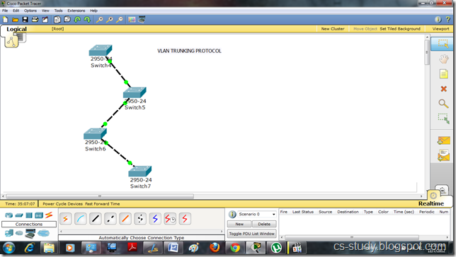
VLAN Trunk Protocol (VTP) reduces administration in a switched network. When you configure a new VLAN on one VTP server, the VLAN is distributed through all switches in the domain. This reduces the need to configure the same VLAN everywhere. Let us apply VTP on packet tracer.
 1
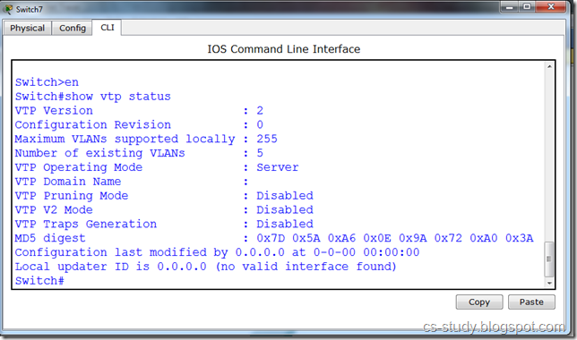
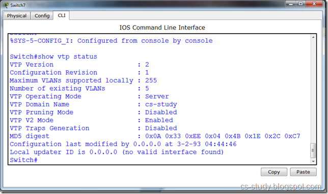
Let us see vtp status by applying the command “show vtp status”.
 forall
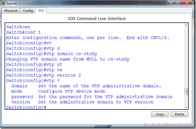
Let us set domain name. In VTP there should be only one domain name through out to synchronize between all the switches.
 2
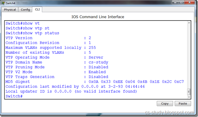
Domain name is set.
3
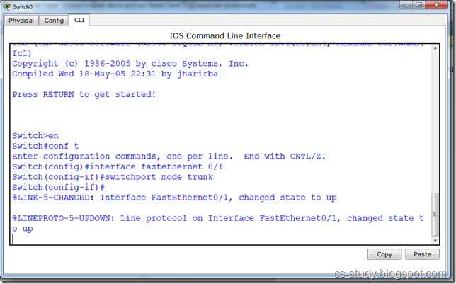
In order for changes made in one switch to take place in other switches as well. we will have to trunk the interfaces. Only those interfaces that are connected.
88
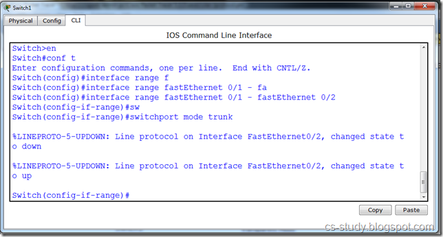
Or we can select a range of interfaces and trunk them.
 99
Now, when we check the status on other switches we can see that the domain name has been set on all the other switches as well.
 aftall
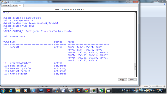
Let us create VLAN.
 4
This vlan is shown in other switch due to the trunking .
 5
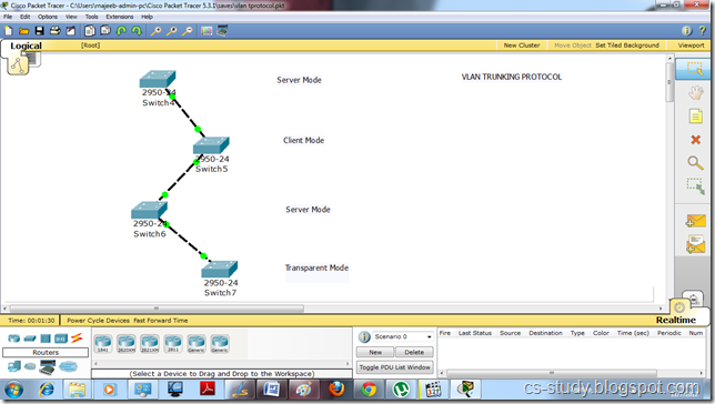
Now, there are three modes in a vtp.
i. Server
ii. Client
iii. Transparent
We are going to apply all three modes on different switches. We can create vlan in server mode, only use them in client mode. But the changes made in transparent mode are independent and does not have affect on other modes.
jj

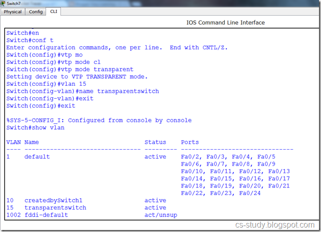
Let us turn the switch 7 to transparent mode and create a vlan in it.
 6
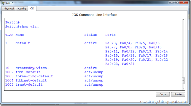
The vlan created in transparent mode is not visible in the other modes.
 7
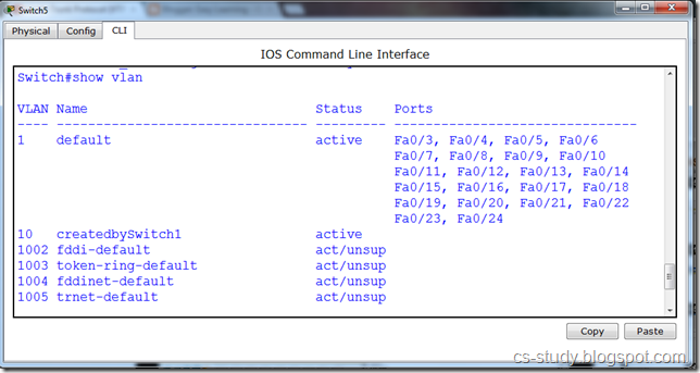
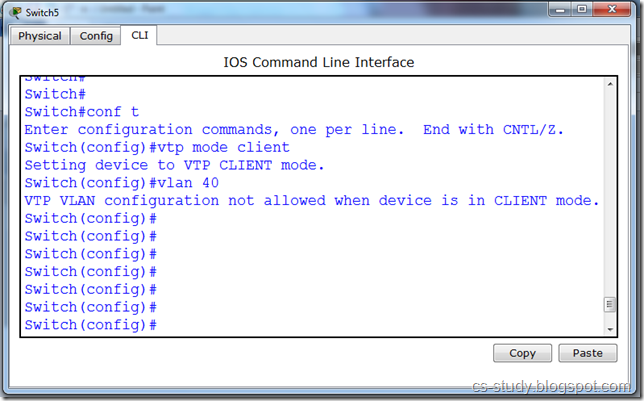
If we change the mode of vtp from server to client , we are unable to create vlan now in the client mode as shown in the message below.
 8

November 6, 2012

Spanning Tree Protocol on Packet Tracer

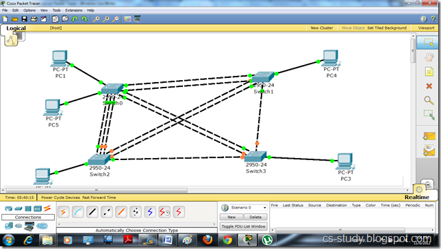
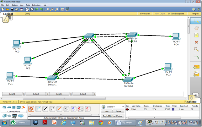
Let us apply STP on packet tracer. Let us develop a basic topology like the one in the following diagram.
y
As we can see in the above diagram that some light are green while others are orange. Y is it so ? We will see that in a moment. Let us try to communicate between two Hosts. Assign IP addresses to all hosts
uu
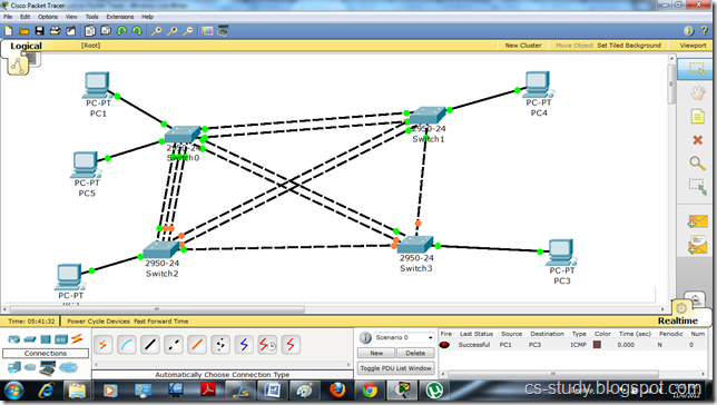
As we can see in the figure below, the communication is successful. It is due to the spanning tree protocol applied on the switch by default. It provides us with the loop free environment. It calculates the cost of each path and provides us with the one that has the minimum cost. That is the reason that some links are up while others are down with the orange light.
uiu
So let us see what happens if we remove the spanning tree protocol from this topology.
fff
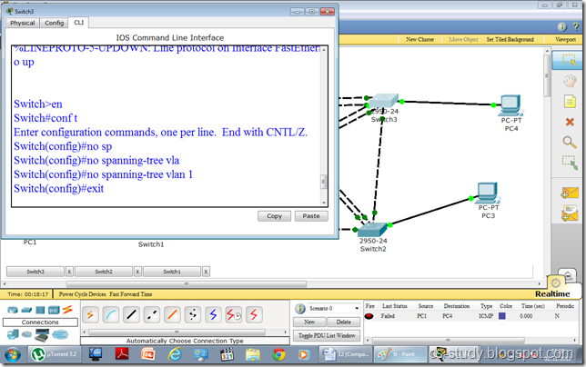
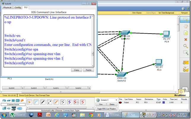
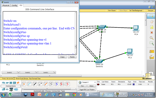
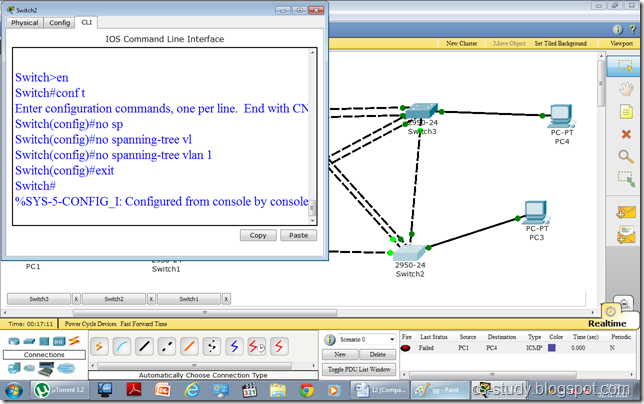
We will remove STP from all the switches one by one.
gfgf

gg
tt
After removing STP, we have observed by the following diagram, a couple of changes. i.e. all the lights are green. In fact, some are dark green. Some lights are blinking, while some are not. This is due to fact that as there is no protocol to decide that which path to choose as we have removed STP.
d
Now that if we try to communicate between any hosts it will fail and communication is disabled.
lmklkjlk

VLAN on Packet Tracer

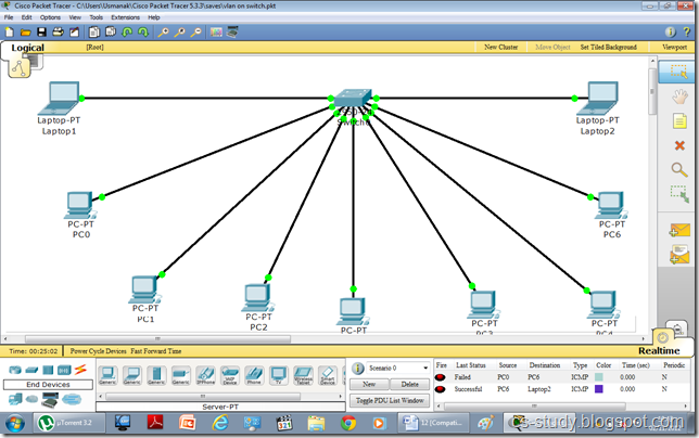
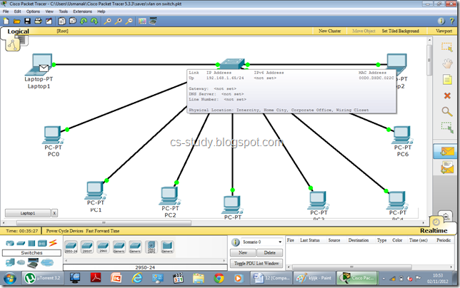
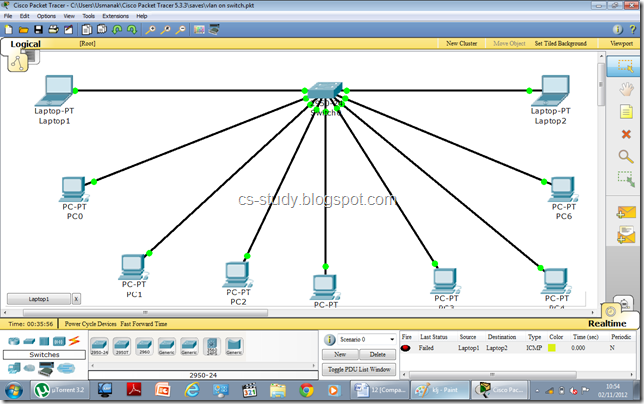
In this tutorial, we are going to apply VLAN on packet tracer. Let us create a topology with one switch and multiple hosts like in the figure below.
1
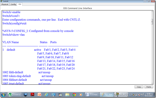
if we go to the switch and enter the command “show vlan ”. It shows the following. 
 afadsfadsf
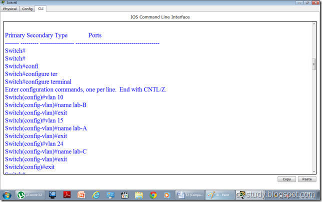
As we can see in the figure above all the interfaces are being displayed and they are all the part of the default vlan 1. Now let us apply vlans on the switch. We are going to create three vlans as follows.
 dsgs
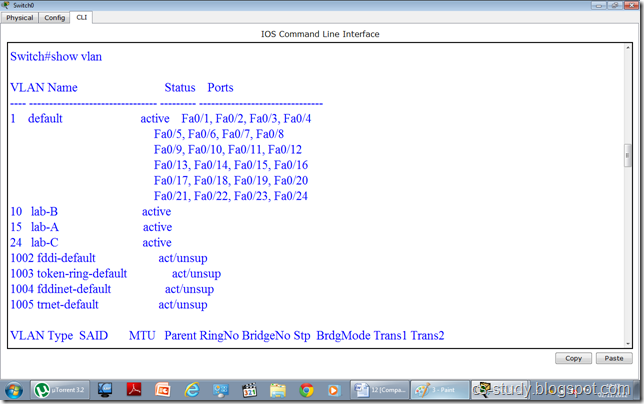
Now, that we have created the vlans. Lets see if they are visible to us.
ds
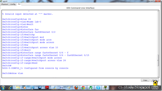
In the above figure, vlans are visible. Now, we are going to assign interfaces to vlans. They are two ways to do this.
i. We can select an interface and assign that interface to a specific vlan
ii. We can select multiple interfaces (range of interfaces) at once and assign those interfaces to vlan.
In the figure below, we have done both of these.

yyy
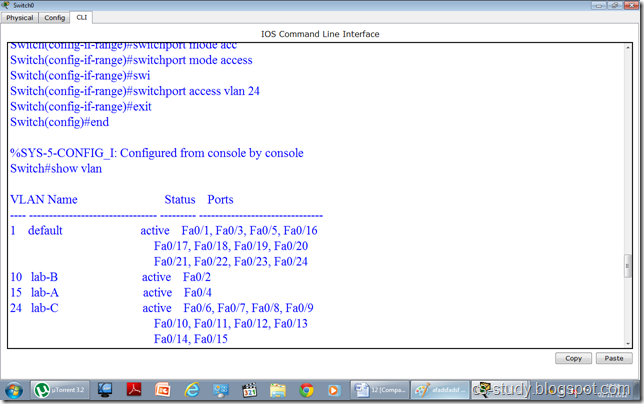
Now, when we write “show vlan “ command and observe it. We will realize that interfaces have been assigned to desired vlans respectively.
 ggggggggg
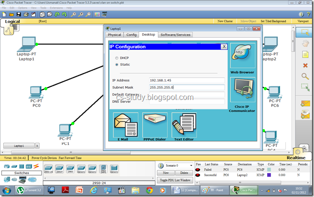
Let us assign IP addresses to PCs. Open the PC.
 fff
Assign IP address.
 kljljk
After assigning IP addresses, when we try to communicate between two PCs belonging to two different vlans, it will fail. Thus, we have achieved our purpose.
 klj
The message sending failure status can be seen in the bottom right corner.
 uu

November 4, 2012

VLAN

VLAN or  Virtual Local Area Network is a phenomenon which is used to logically separate or combine a network. It is used to configured one or more devices, so that they can communicate, as if they were attached to the same wire, when in fact they are located on a number of different LAN segments. Because VLANs are based on logical instead of physical connections, they are extremely flexible. 

What is VLAN

VLAN is a concept of partitioning of a physical network, so that distinct broadcast domains are created. This is usually achieved on switch or router devices. Simpler devices only support partitioning on a port level, so sharing VLANs across devices requires running dedicated cabling for each VLAN.
Grouping hosts with a common set of requirements regardless of their physical location by VLAN can greatly simplify network design. A VLAN has the same attributes as a physical local area network (LAN), but it allows for end stations to be grouped together more easily even if they are not on the same network switch. Without VLANs, a switch considers all interfaces on the switch to be in the same broadcast domain.To physically replicate the functions of a VLAN would require a separate, parallel collection of network cables and equipment separate from the primary network.

 How VLAN's work

When a LAN bridge receives data from a workstation, it tags the data with a VLAN identifier indicating the VLAN from which the data came. This is called explicit tagging. It is also possible to determine to which VLAN the data received belongs using implicit tagging. In implicit tagging the data is not tagged, but the VLAN from which the data came is determined based on other information like the port on which the data arrived. Tagging can be based on the port from which it came, the source Media Access Control (MAC) field, the source network address, or some other field or combination of fields. VLAN's are classified based on the method used. To be able to do the tagging of data using any of the methods, the bridge would have to keep an updated database containing a mapping between VLAN's and whichever field is used for tagging. For example, if tagging is by port, the database should indicate which ports belong to which VLAN. This database is called a filtering database. Bridges would have to be able to maintain this database and also to make sure that all the bridges on the LAN have the same information in each of their databases. The bridge determines where the data is to go next based on normal LAN operations. Once the bridge determines where the data is to go, it now needs to determine whether the VLAN identifier should be added to the data and sent. If the data is to go to a device that knows about VLAN implementation (VLAN-aware), the VLAN identifier is added to the data. If it is to go to a device that has no knowledge of VLAN implementation (VLAN-unaware), the bridge sends the data without the VLAN identifier.


Why use VLAN's?

VLAN offer a number of advantages over traditional LAN.

    Physical topology independence

    VLANs provide independence from the physical topology of the network by allowing physically diverse workgroups to be logically connected within a single broadcast domain. If the physical infrastructure is already in place, it now becomes a simple matter to add ports in new locations to existing VLANs if a department expands or relocates. These assignments can take place in advance of the move, and it is then a simple matter to move devices with their existing configurations from one location to another. The old ports can then be "decommissioned" for future use, or reused by the department for new users on the VLAN.

    Performance
    In networks where traffic consists of a high percentage of broadcasts and multicasts, VLAN's can reduce the need to send such traffic to unnecessary destinations. For example, in a broadcast domain consisting of 10 users, if the broadcast traffic is intended only for 5 of the users, then placing those 5 users on a separate VLAN can reduce traffic.
    Compared to switches, routers require more processing of incoming traffic. As the volume of traffic passing through the routers increases, so does the latency in the routers, which results in reduced performance. The use of VLAN's reduces the number of routers needed, since VLAN's create broadcast domains using switches instead of routers. Switched networks by nature will increase performance over shared media devices in use today, primarily by reducing the size of collision domains. Grouping users into logical networks will also increase performance by limiting broadcast traffic to users performing similar functions or within individual workgroups. Additionally, less traffic will need to be routed, and the latency added by routers will be reduced

    Formation of Virtual Workgroups
    Nowadays, it is common to find cross-functional product development teams with members from different departments such as marketing, sales, accounting, and research. These workgroups are usually formed for a short period of time. During this period, communication between members of the workgroup will be high. To contain broadcasts and multicasts within the workgroup, a VLAN can be set up for them. With VLAN's it is easier to place members of a workgroup together. Without VLAN's, the only way this would be possible is to physically move all the members of the workgroup closer together.
    Despite this saving, VLAN's add a layer of administrative complexity, since it now becomes necessary to manage virtual workgroups.

    Reduced Cost
    VLAN's can be used to create broadcast domains which eliminate the need for expensive routers.

    Security
    Periodically, sensitive data may be broadcast on a network. In such cases, placing only those users who can have access to that data on a VLAN can reduce the chances of an outsider gaining access to the data. VLAN's can also be used to control broadcast domains, set up firewalls, restrict access, and inform the network manager of an intrusion.

    Improved manageability
    VLANs provide an easy, flexible, less costly way to modify logical groups in changing environments. VLANs make large networks more manageable by allowing centralized configuration of devices located in physically diverse locations.

C program to Read From a File

#include <stdio.h> #include <stdlib.h> void main() {     FILE *fptr;     char filename[15];     char ch;   ...