November 11, 2013

Planning a Network with Different Users, Hosts, and Services

Objective
The objective of this lab is to demonstrate the basics of designing a network, taking into consideration the users, services, and locations of the hosts.
Overview
Optimizing the design of a network is a major issue. Simulations are usually used to analyze the conceptual design of the network. The initial conceptual design is usually refined several times until a final decision is made to implement the design. The objective is to have a design that maximizes the network performance, taking into consideration the cost constraints and the required services to be offered to different types of users. After the network has been implemented, network optimization should be performed periodically throughout the lifetime of the network to ensure maximum performance of the network and to monitor the utilization of the network resources.
In this lab you will design a network for a company that has four departments: Research, Engineering, E-Commerce, and Sales. You will utilize a LAN model that allows you to simulate multiple clients and servers in one simulation object. This model dramatically reduces both the amount of configuration work you need to perform and the amount of memory needed to execute the simulation. You will be able to define a profile that specifies the pattern of applications employed by the users of each department in the company. By the end of this lab, you will be able to study how different design decisions can affect the performance of the network.
Procedure
Create a New Project
1. Start OPNET IT Guru Academic Edition ⇒ Choose New from the File menu.
2. Select Project and click OK ⇒ Name the project <your initials>_NetDesign, and the scenario SimpleNetwork ⇒ Click OK.
3. In the Startup Wizard: Initial Topology dialog box, make sure that Create Empty Scenario is selected Click Next Choose Campus from the Network Scale list ⇒ Click Next ⇒ Choose Miles from the Size drop-down menu and assign 1 for both X Span and Y Span ⇒ Click Next twice ⇒ Click OK.
Create and Configure the Network
Application Config is used to specify applications that will be used to configure users profiles.
Profile Config describes the activity patterns of a user or group of users in terms of the applications used over a period of time. You must define the applications using the Application Config object before using this object.
Initialize the Network:
1. The Object Palette dialog box should be now on the top of your project space. If it
is not there, open it by clickingclip_image007
. Make sure that the internet_toolbox is selected from the pull-down menu on the object palette.
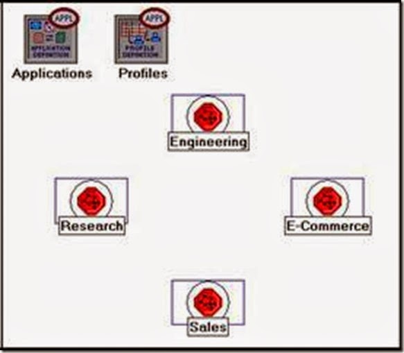
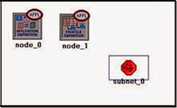
2. Add to the project workspace the following objects from the palette: Application Config, Profile Config and a subnet.
a. To add an object from a palette, click its icon in the object palette ⇒ Move your mouse to the workspace ⇒ Left-click to place the object. Right-click when finished. The workspace should contain the following three objects:
clip_image009

3. Close the Object Palette dialog box and save your project.
Configure the Services:
  1. Right-click on the Application Config node ⇒ Edit Attributes ⇒ Change the name attribute to Applications Change the Application Definitions attribute to Default ⇒ Click OK.
  1. Right-click on the Profile Config node ⇒ Edit Attributes ⇒ Change the name attribute to Profiles ⇒ Change the Profile Configuration attribute to Sample Profiles Click OK.
Sample Profiles provides patterns of applications employed by users such as engineers, researchers, salespeople, and multimedia users.
Configure a Subnet:
  1. Right-click on the subnet node ⇒ Edit Attributes ⇒ Change the name attribute to Engineering and click OK.
  1. Double-click on the Engineering node. You get an empty workspace, indicating that the subnet contains no objects.
  1. Open the object palette clip_image010 and make sure it is still set to internet_toolbox.
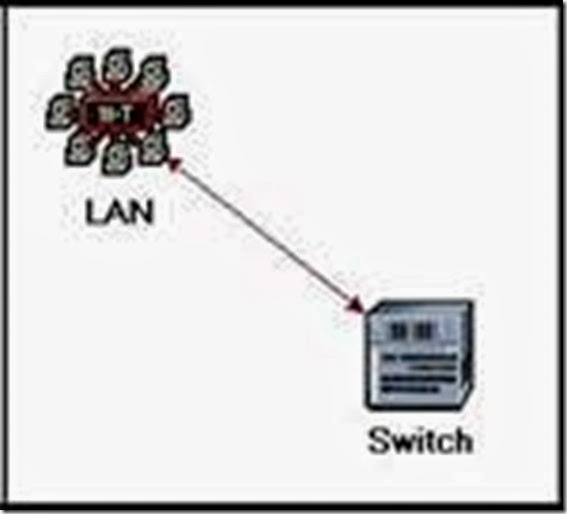
  1. Add the following items to the subnet workspace: 10BaseT LAN, ethernet16 Switch, and a 10BaseT link to connect the LAN with the Switch Close the palette.
  1. Right-click on the 10BaseT LAN node ⇒ Edit Attributes ⇒ Change the name attribute to LAN ⇒ Observe that the Number of Workstations attribute has a value of 10. Click in the Value column for the Application: Supported Profiles attribute, and select Edit. You should get a table in which you should do the following:
    1. Set the number of rows to 1.
    1. Set the Profile Name to Engineer. Note: Engineer is one of the “sample” profiles provided within the Profile Config object.
    1. Click OK twice.
The object we just created is equivalent to a 10-workstation star topology LAN. The traffic generated from the users of this LAN resembles that generated by “engineers.”
  1. Rename the ethernet16 Switch to Switch.
  1. The subnet should look like the shown one.
  1. Save your project.
clip_image012
Configure All Departments:
  1. Now you have completed the configuration of the Engineering department subnet. To go back to the main project space, click the Go to the higher level clip_image014 button.
The subnets of the other departments in the company should be similar to the engineering one except for the supported profiles.
  1. Make three copies of the Engineering subnet we just created: Click on the Engineering node From the Edit menu, select Copy From the Edit menu, select Paste three times, placing the subnet in the workspace after each, to create the new subnets.
3. Rename (right-click on the subnet and select Set Name) and arrange the subnets as shown below:
clip_image016


  1. Double-click the Research node ⇒ Edit the attributes of its LANEdit the value of the Application: Supported Profiles attribute ⇒ Change the value of the Profile Name from Engineer to Researcher ⇒ Click OK twice ⇒ Go to the higher level by clicking the clip_image017 button.
  1. Repeat step 4 with the Sales node and assign to its Profile Name the profile
Sales Person.
6. Repeat step 4 with the E-Commerce node and assign to its Profile Name the profile E-commerce Customer.
  1. Save your project.
Configure the Servers:
Now we need to implement a subnet that contains the servers. The servers have to support the applications defined in the profiles we deployed. You can double-check those applications by editing the attributes of our Profile node. Inspect each row under the Applications hierarchy, which in turn, is under the Profile Configuration hierarchy. You will see that we need servers that support the following applications: Web browsing, Email, Telnet, File Transfer, Database, and File Print.
  1. Open the Object Palette clip_image007[1] and add a new subnet ⇒ Rename the new subnet to Servers ⇒ Double-click the Servers node to enter its workspace.
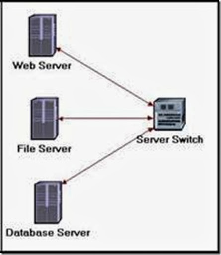
2. From the Object Palette, add three ethernet_servers, one ethernet16_switch, and three 10BaseT links to connect the servers with the switch.
  1. Close the Object Palette.
  1. Rename the servers and the switch as follows:
clip_image019

  1. Right-click on each one of the above servers and Edit the value of the
Application: Supported Services attribute.
i. For the Web Server add four rows to support the following services: Web Browsing (Light HTTP1.1), Web Browsing (Heavy HTTP1.1), Email (Light), and Telnet Session (Light).
ii. For the File Server add two rows to support the following services: File Transfer (Light) and File Print (Light).
iii. For the Database Server add one row to support the following service:
Database Access (Light).
6. Go back to the project space by clicking the Go to the higher level clip_image017[1] button.
  1. Save your project.
Connect the Subnets:
Now all subnets are ready to be connected together.
  1. Open the Object Palette clip_image020 and add four 100BaseT links to connect the subnets of the departments to the Servers subnet.
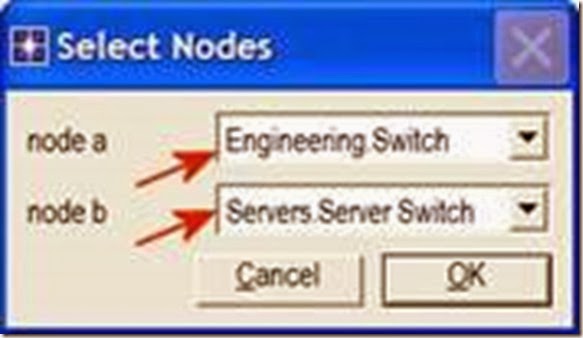
As you create each link, make sure that it is configured to connect the “switches” in both subnets to each other. Do this by choosing them from the drop-down menus as follows:
clip_image022

  1. Close the Object Palette.
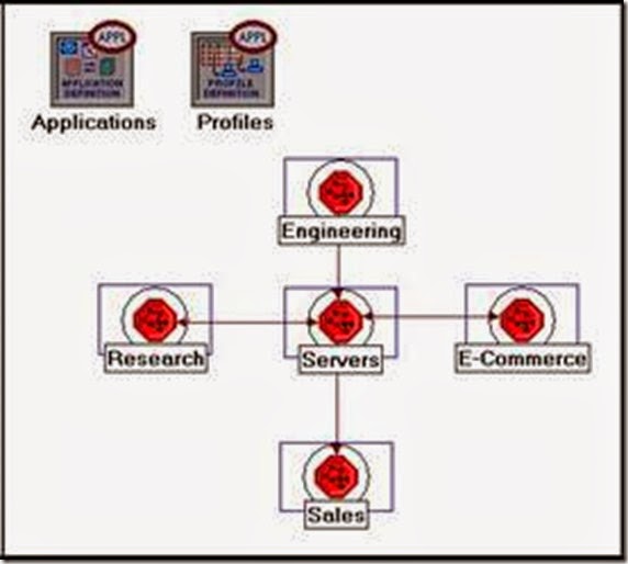
  1. Now your network should resemble the following one:
clip_image024
4. Save your project.
Choose the Statistics
To test the performance of our network we will collect one of the many available statistics as follows:
1. Right-click anywhere in the project workspace and select Choose Individual Statistics from the pop-up menu.
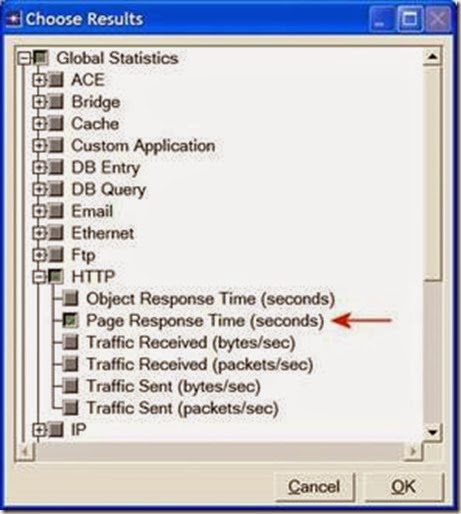
2. In the Choose Results dialog box, choose the following statistic:
clip_image026

Page Response Time is the required time to retrieve the entire page.
3. Click OK.
Configure the Simulation
Here we need to configure the duration of the simulation:
1. Click on the Configure/Run Simulation clip_image028 button.
2. Set the duration to be 30.0 minutes.
3. Press OK.
Duplicate the Scenario
Link utilization is the percentage of the used link bandwidth.
In the network we just created we assumed that there is no background traffic already in the links. In real networks, the links usually have some existing background traffic. We will create a duplicate of the SimpleNetwork scenario but with background utilization in the 100BaseT links.
  1. Select Duplicate Scenario from the Scenarios menu and give it the name
BusyNetwork Click OK.
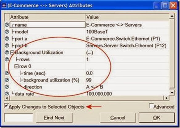
2. Select all the 100BaseT links simultaneously (click on all of them while holding the Shift key) Right-click on anyone of them Edit Attributes Check the
Apply Changes to Selected Objects check box.
3. Expand the hierarchy of the Background Utilization attribute ⇒ Expand the row 0 hierarchy Assign 99 to the background utilization (%) as shown below.
clip_image030
4. Click OK.
5. Save your project.
Run the Simulation
To run the simulation for both scenarios simultaneously:
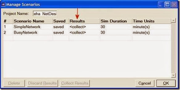
1. Go to the Scenarios menu ⇒ Select Manage Scenarios.
2. Change the values under the Results column to <collect> (or <recollect>) for both scenarios. Compare to the following figure.
clip_image032

3. Click OK to run the two simulations. Depending on the speed of your processor, this may take several seconds to complete.
4. After the two simulation runs complete (one for each scenario), click Close.
5. Save your project.
View the Results
To view and analyze the results:
1. Select Compare Results from the Results menu.
2. Change the drop-down menu in the lower-right part of the Compare Results dialog box from As Is to time_average as shown.
clip_image034

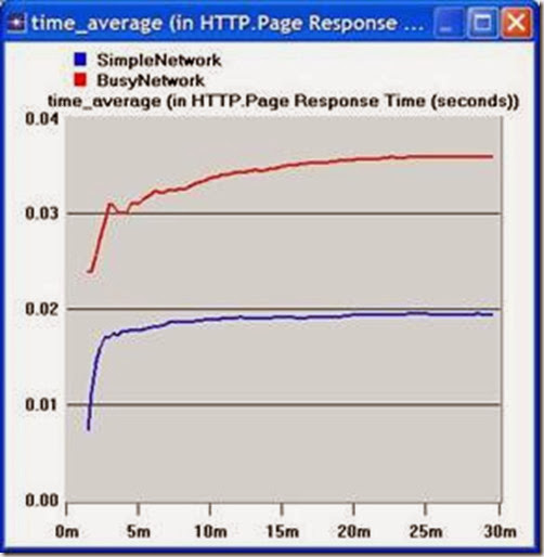
3. Select the Page Response Time (seconds) statistic and click Show. The resulting graph should resemble the one below. (Note: Results may vary slightly due to different node placement.)
clip_image036
Questions
1) Analyze the result we obtained regarding the HTTP page response time. Collect four other statistics, of your choice, and rerun the simulation of the Simple and the Busy network scenarios. Get the graphs that compare the collected statistics. Comment on these results.
2) In the BusyNetwork scenario, study the utilization% of the CPUs in the servers (Right-click on each server and select Choose Individual StatisticsCPUUtilization).
3) Create a new scenario as a duplicate of the BusyNetwork scenario. Name the new scenario Q3_OneServer. Replace the three servers with only one server that supports all required services. Study the utilization% of that server’s CPU. Compare this utilization with the three CPU utilizations you obtained in the previous question.
4) Create a new scenario as a duplicate of the BusyNetwork scenario. Name the new scenario Q4_FasterNetwork. In the Q4_FasterNetwork scenario, replace all 100BaseT links in the network with 10Gbps Ethernet links and replace all 10BaseT links with 100BaseT links. Study how increasing the bandwidth of the links affects the performance of the network in the new scenario (e.g., compare the HTTP page response time in the new scenario with that of the BusyNetwork).
A Set of Local Area Networks Interconnected by Switches

Objective
This lab is designed to demonstrate the implementation of switched local area networks. The simulation in this lab will help you examine the performance of different implementations of local area networks connected by switches and hubs.

Overview
There is a limit to how many hosts can be attached to a single network and to the size of a geographic area that a single network can serve. Computer networks use switches to enable the communication between one host and another, even when no direct connection exists between those hosts. A switch is a device with several inputs and outputs leading to and from the hosts that the switch interconnects. The core job of a switch is to take packets that arrive on an input and forward (or switch) them to the right output so that they will reach their appropriate destination.
A key problem that a switch must deal with is the finite bandwidth of its outputs. If packets destined for a certain output arrive at a switch and their arrival rate exceeds the capacity of that output, then we have a problem of contention. In this case, the switch will queue, or buffer, packets until the contention subsides. If it lasts too long, however, the switch will run out of buffer space and be forced to discard packets. When packets are discarded too frequently, the switch is said to be congested.
In this lab you will set up switched LANs using two different switching devices: hubs and switches. A hub forwards the packet that arrives on any of its inputs on all the outputs regardless of the destination of the packet. On the other hand, a switch forwards incoming packets to one or more outputs depending on the destination(s) of the packets. You will study how the throughput and collision of packets in a switched network are affected by the configuration of the network and the types of switching devices that are used.
Procedure
Create a New Project
1. Start the OPNET IT Guru Academic Edition ⇒ Choose New from the File menu.
2. Select Project and click OK ⇒ Name the project <your initials>_SwitchedLAN, and the scenario OnlyHub ⇒ Click OK.
3. In the Startup Wizard: Initial Topology dialog box, make sure that Create Empty Scenario is selected Click Next Choose Office from the Network Scale list ⇒ Click Next three times ⇒ Click OK.
4. Close the Object Palette dialog box.
Create the Network
The prefix ethernet16_ indicates that the device supports up to 16 Ethernet connections.
The 10BaseT link represents an Ethernet connection operating at 10 Mbps.
To create our switched LAN:
  1. Select TopologyRapid Configuration. From the drop-down menu choose Star and click OK.
2. Click the Select Models button in the Rapid Configuration dialog box. From the Model List drop-down menu choose ethernet and click OK.
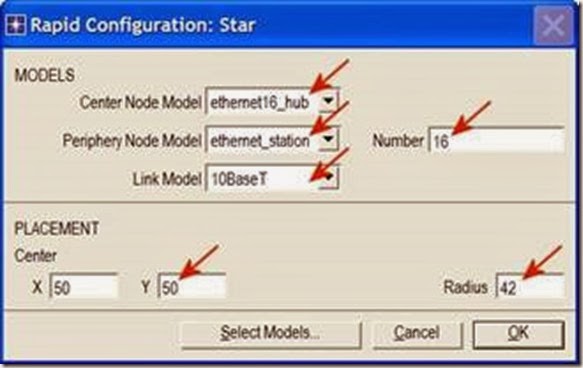
3. In the Rapid Configuration dialog box, set the following five values: Center Node Model = ethernet16_hub, Periphery Node Model = ethernet_station, Link Model = 10BaseT, Number=16, Y=50, and Radius = 42 Click OK.
clip_image008

4. Right-click on node_16, which is the hub ⇒ Edit Attributes ⇒ Change the name attribute to Hub1 and click OK.
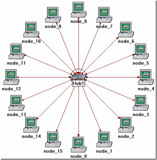
5. Now that you have created the network, it should look like the following one.
6. Make sure to save your project.
9898

Configure the Network Nodes
Here you will configure the traffic generated by the stations.
1. Right-click on any of the 16 stations (node_0 to node_15) ⇒ Select Similar Nodes. Now all stations in the network are selected.
2. Right-click on any of the 16 stations ⇒ Edit Attributes.
a. Check the Apply Changes to Selected Objects check box. This is important to avoid reconfiguring each node individually.
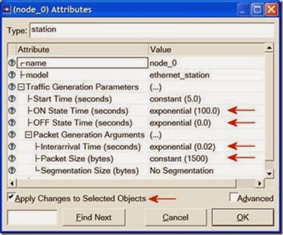
3. Expand the hierarchies of the Traffic Generation Parameters attribute and the Packet Generation Arguments attribute Set the following four values:
clip_image012

4. Click OK to close the attribute editing window(s). Save your project.
Choose Statistics
To choose the statistics to be collected during the simulation:
1. Right-click anywhere in the project workspace and select Choose Individual Statistics from the pop-up menu.
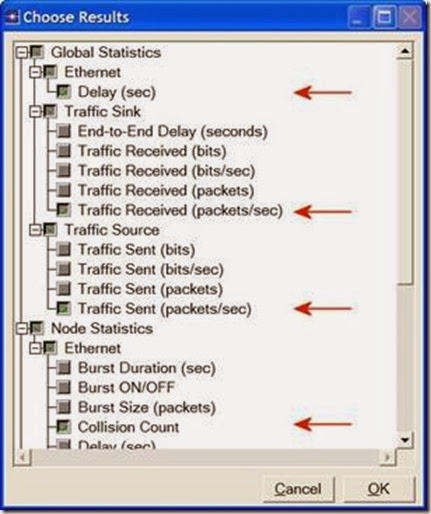
2. In the Choose Results dialog box, choose the following four statistics:
The Ethernet Delay represents the end to end delay of all packets received by all the stations.
clip_image014

Traffic Received (in packets/sec) by the traffic sinks across all nodes.
Traffic Sent (in packets/sec) by the traffic sources across all nodes.
Collision Count is the total number of collisions encountered by the hub during packet transmissions.
3. Click OK.
Configure the Simulation
Here we need to configure the duration of the simulation:
1. Click on the Configure/Run Simulation button: clip_image016
2. Set the duration to be 2.0 minutes.
3. Click OK.
Duplicate the Scenario
The network we just created utilizes only one hub to connect the 16 stations. We need to create another network that utilizes a switch and see how this will affect the performance of the network. To do that we will create a duplicate of the current network:
1. Select Duplicate Scenario from the Scenarios menu and give it the name HubAndSwitch Click OK.
2. Open the Object Palette by clicking on clip_image018. Make sure that Ethernet is selected in the pull-down menu on the object palette.
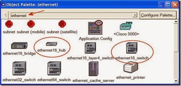
3. We need to place a hub and a switch in the new scenario. (They are circled in the following figure.)
clip_image020

4. To add the Hub, click its icon in the object palette ⇒ Move your mouse to the workspace ⇒ Click to drop the hub at a location you select. Right-click to indicate you are done deploying hub objects.
5. Similarly, add the Switch
6. Close the Object Palette.
7. Right-click on the new hub ⇒ Edit Attributes ⇒ Change the name attribute to Hub2 and click OK.
8. Right-click on the switch ⇒ Edit Attributes ⇒ Change the name attribute to Switch and click OK.
9. Reconfigure the network of the HubAndSwitch scenario so that it looks like the following one.
Hints:
a. To remove a link, select it and choose Cut from the Edit menu (or simply hit the Delete key). You can select multiple links and delete all of them at once.
b. To add a new link, use the 10BaseT link available in the Object Palette.
image


10. Save your project.
Run the Simulation
To run the simulation for both scenarios simultaneously:
1. Select Manage Scenarios from the Scenarios menu.
2. Change the values under the Results column to <collect> (or <recollect>) for both scenarios. Compare to the following figure.
clip_image024

3. Click OK to run the two simulations. Depending on the speed of your processor, this may take several minutes to complete.
4. After the two simulation runs complete, one for each scenario, click Close.
5. Save your project.
View the Results
To view and analyze the results:
1. Select Compare Results from the Results menu.
2. Change the drop-down menu in the lower-right part of the Compare Results dialog box from As Is to time_average, as shown.
clip_image026

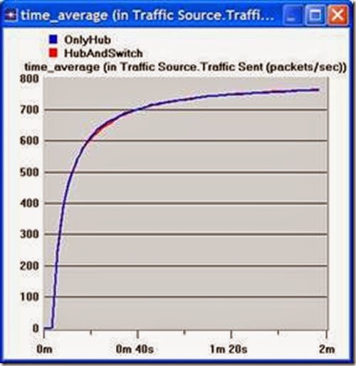
3. Select the Traffic Sent (packets/sec) statistic and click Show. The resulting graph should resemble the one below. As you can see, the traffic sent in both scenarios is almost identical.
clip_image028
4. Select the Traffic Received (packets/sec) statistic and click Show. The resulting graph should resemble the one below. As you see, the traffic received with the second scenario, HubAndSwitch, is higher than that of the OnlyHub scenario.
clip_image030

5. Select the Delay (sec) statistic and click Show. The resulting graph should resemble the one below. (Note: Result may vary slightly due to different node placement.)
clip_image032

6. Select the Collision Count statistic for Hub1 and click Show.
7. On the resulting graph right-click anywhere on the graph area ⇒ Choose Add Statistic Expand the hierarchies as shown below Select the Collision Count statistic for Hub2 Change As Is to time_average Click Add.
clip_image034
8. The resulting graph should resemble the one below.
clip_image036
9. Save your project.
Note:
time_average is the average value over time of the values generated during the collection window. This average is performed assuming a “sample-and-hold” behavior of the data set (i.e., each value is weighted by the amount of time separating it from the following update and the sum of all the weighted values is divided by the width of the collection window). For example, suppose you have a 1-second bucket in which 10 values have been generated. The first 7 values were generated between 0 and 0.3 seconds, the 8th value at 0.4 seconds, the 9th value at 0.6 seconds , and the 10th at 0.99 seconds. Because the last 3 values have higher durations, they are weighted more heavily in calculating the time average.

November 5, 2013

Installation of IT Guru

The installation of IT Guru can be a bit challenging. The first part is to do the registration online. Only then you will recieve the link to download opnet IT Guru. So, lets walk through it.
Type in Google as shown below. Click the first link.

1
The following main IT Guru page will open.


At the bottom, there is a button “Register and Download”. Click it.
 2
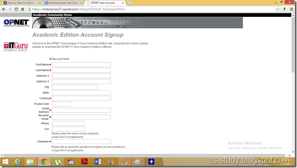
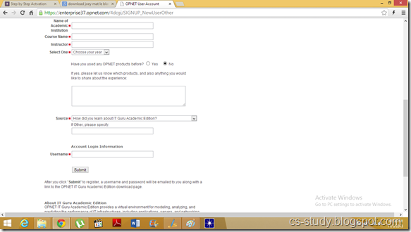
The following registration page will open. Fill it with correct credentials. Provide valid email id.
 3
Registration continued. …
 4
After registration, You will recieve an email from the OPNET IT Guru. In which you will recieve your password. And you will recieve your download link as shown below.
 5
In the above diagram, instead of “xxxx…..” , you will recieve your actual username and password. 
After click on the link above. It will start downloading the setup. Its about 200 Mb. Download it and then install the IT Guru. When you are done with IT Guru installation, run it.
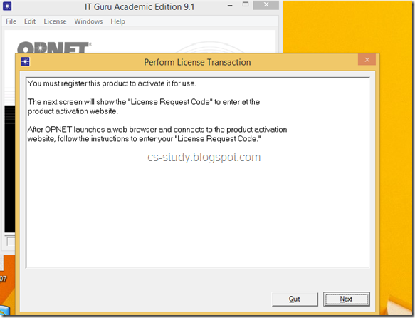
It will show you the screen to either quit or go in the license management. Click license management you will see the following screen.

1
Click next, in the above screen. It will also open the web browser for you and ask for authentication. Here you will provide the username and password that you recieved in your email.
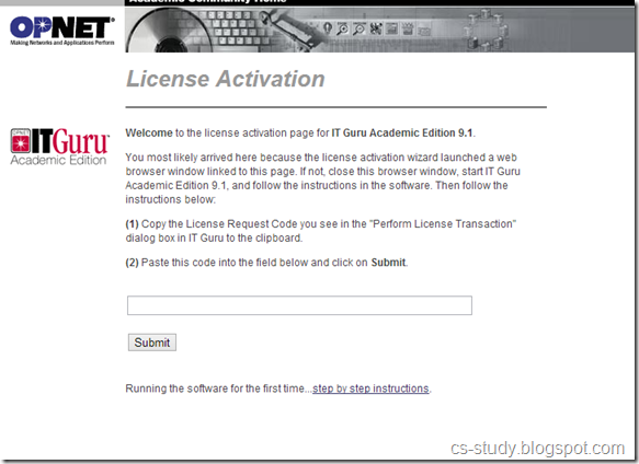
In the below window, you will enter the key which will be displayed on the IT Guru.
 2
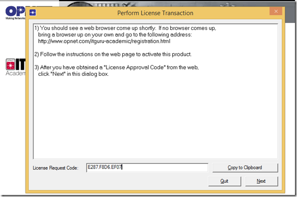
Provide the following key in the browser. As shown in the above window.
3
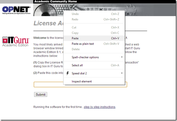
Paste it there.
 4
And click submit.
 5
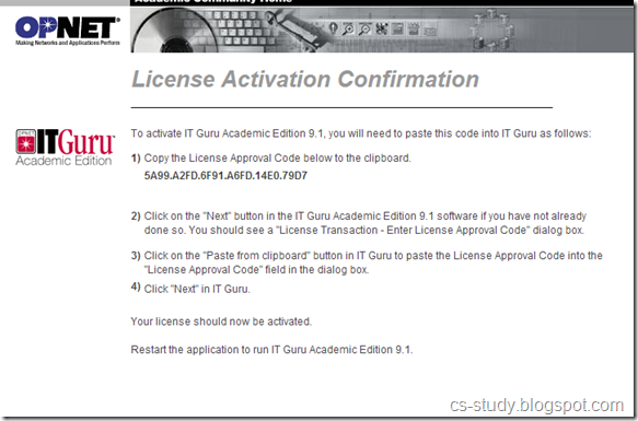
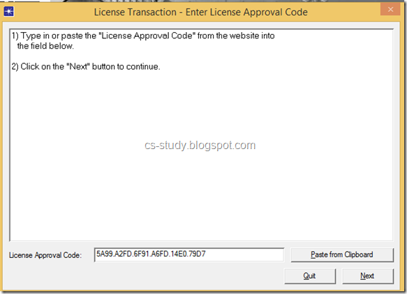
You will be provided with the key.  You need to copy that key and paste it in the IT Guru as shown below and click next.
 6
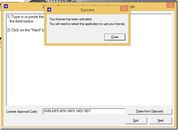
There, you go , IT Guru has been activated with key. Now, you can use it. Cheers.
 7
 

October 27, 2013

Abstraction

Real life objects have a lot of attributes and many kind of behaviors but most of the time we are interested in only that part of the objects that is related to the problem we are currently going to solve, for example in implementing a school system we don’t need to take care of the personnel life of a student or a teacher as it will not effect our system in any way so we will see these objects in the perspective of school system and will ignore their other characteristics, this concept is called “Abstraction”. Abstraction is a way to cope with complexity and it is used to simplify things.

Principle of abstraction:

“Capture only those details about an object that are relevant to current perspective”
Abstraction Example:
Suppose we want to implement abstraction for the following statement.
“Ali is a PhD student and teaches BS students”
Here object Ali has two perspectives one is his student perspective and second is his teacher perspective.
We can sum up Ali’s attributes as follows,
Name
Age
Student Roll No
Year of Study
CGPA
Employee ID
Designation
Salary
As you can see out of all these listed attributes some belong to Ali’s student perspective(Roll No, CGPA, Year of study) and some belong to Ali’s teacher perspective(Employee ID, Designation, Salary).
Similarly we can sum up Ali’s behavior as follows,

Study
DevelopExam
GiveExam
TakeExam
PlaySports
Eat
DeliverLecture
Walk
As was the case with attributes of object Ali, its behavior can also be divided in Ali’s student perspective as well as Ali’s teacher perspective.
Student’s Perspective
Attributes:
- Name - Employee ID
- Student Roll No - Designation
- Year of Study - Salary
- CGPA - Age
Behaviour:
- Study - DevelopExam
- GiveExam - TakeExam
- PlaySports - Eat
- DeliverLecture - Walk
Teacher’s Perspective
Attributes:
- Name - Employee ID
- Student Roll No - Designation
- Year of Study - Salary
- CGPA - Age
Behaviour:
- Study - DevelopExam
- GiveExam - TakeExam
- PlaySports - Eat
- DeliverLecture - Walk
A cat can be viewed with different perspectives
Ordinary Perspective
A pet animal with
Four Legs
A Tail
Two Ears
Sharp Teeth
Surgeon’s Perspective
A being with
A Skeleton
Heart
Kidney
Stomach
A car can be viewed with different perspectives.
From driver’s point of view, it has an accelerator, a brake, a clutch, a gear box etc.
From engineer’s point of view, it has an engine, a fuel pump, a rotary motor, shocks etc.
clip_image002
Driver’s View
clip_image004
Engineer’s View

Abstraction – Advantages


Abstraction has following major advantages.
  1. It helps us understanding and solving a problem using object oriented approach as it hides extra irrelevant details of objects.
  1. Focusing on single perspective of an object provides us freedom to change implementation for other aspects of for an object later.
Similar to Encapsulation Abstraction is also used for achieving information hiding as we show only relevant details to related objects, and hide other details.


Information Hiding and Encapsulation in OOP

Information hiding is one of the most important principles of OOP inspired from real life which says that all information should not be accessible to all persons. Private information should only be accessible to its owner.
By Information Hiding we mean “Showing only those details to the outside world which are necessary for the outside world and hiding all other details from the outside world.”
Real Life Examples of Information Hiding
  1. Your name and other personal information is stored in your brain we can’t access this information directly. For getting this information we need to ask you about it and it will be up to you how much details you would like to share with us.
  1. An email server may have account information of millions of people but it will share only our account information with us if we request it to send anyone else accounts information our request will be refused.
  1. A phone SIM card may store several phone numbers but we can’t read the numbers directly from the SIM card rather phone-set reads this information for us and if the owner of this phone has not allowed others to see the numbers saved in this phone we will not be able to see those phone numbers using phone.
In object oriented programming approach we have objects with their attributes and behaviors that are hidden from other classes, so we can say that object oriented programming follows the principle of information hiding.
In the perspective of Object Oriented Programming Information Hiding is,
“Hiding the object details (state and behavior) from the users”
Here by users we mean “an object” of another class that is calling functions of this class using the reference of this class object or it may be some other program in which we are using this class.
Information Hiding is achieved in Object Oriented Programming using the following principles,
· All information related to an object is stored within the object
· It is hidden from the outside world
· It can only be manipulated by the object itself
Advantages of Information Hiding
Following are two major advantages of information hiding. It simplifies our Object Oriented Model:
As we saw earlier that our object oriented model only had objects and their interactions hiding implementation details so it makes it easier for everyone to understand our object oriented model. It is a barrier against change propagation. As implementation of functions is limited to our class and we have only given the name of functions to user along with description of parameters so if we change implementation of function it doesn’t affect the object oriented model.
We can achieve information hiding using Encapsulation and Abstraction, so we see these two concepts in detail now.

Encapsulation means “we have enclosed all the characteristics of an object in the object itself”.
Encapsulation and information hiding are much related concepts (information hiding is achieved using Encapsulation). We have seen in previous lecture that object characteristics include data members and behavior of the object in the form of functions. So we can say that Data and Behavior are tightly coupled inside an object and both the information structure and implementation details of its operations are hidden from the outer world.
Examples of Encapsulation
Consider the same example of object Ali of previous lecture we described it as follows.

Ali
Characteristics (attributes)
· Name
· Age
Behavior (operations)
· Walks
· Eats

You can see that Ali stores his personal information in itself and its behavior is also implemented in it. Now it is up to object Ali whether he wants to share that information with outside world or not. Same thing stands for its behavior if some other object in real life wants to use his behavior of walking it can not use it without the permission of Ali. So we say that attributes and behavior of Ali are encapsulated in it. Any other object don’t know about these things unless Ali share this information with that object through an interface. Same concept also applies to phone which has some data and behavior of showing that data to user we can only access the information stored in the phone if phone interface allow us to do so.
Advantages of Encapsulation
The following are the main advantages of Encapsulation,
  1. Simplicity and clarity
As all data and functions are stored in the objects so there is no data or function around in program that is not part of any object and is this way it becomes very easy to understand the purpose of each data member and function in an object.
  1. Low complexity
As data members and functions are hidden in objects and each object has a specific behavior so there is less complexity in code there will be no such situations that a functions is using some other function and that functions is using some other function.
  1. Better understanding
Everyone will be able to understand whole scenario by simple looking into object diagrams without any issue as each object has specific role and specific relation with other objects.


C program to Read From a File

#include <stdio.h> #include <stdlib.h> void main() {     FILE *fptr;     char filename[15];     char ch;   ...