Showing posts with label Packet Tracer Tutorial. Show all posts

November 7, 2012

VTP on Packet Tracer

VLAN Trunk Protocol (VTP) reduces administration in a switched network. When you configure a new VLAN on one VTP server, the VLAN is distributed through all switches in the domain. This reduces the need to configure the same VLAN everywhere. Let us apply VTP on packet tracer.
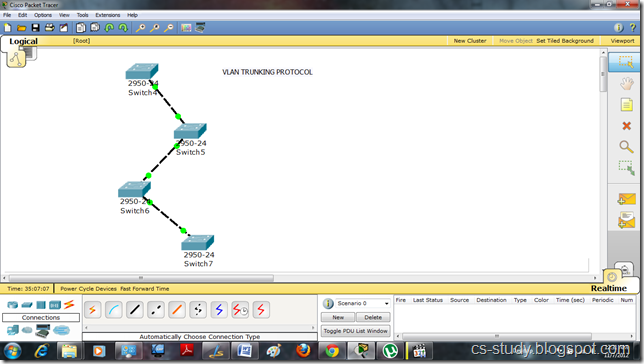
 1
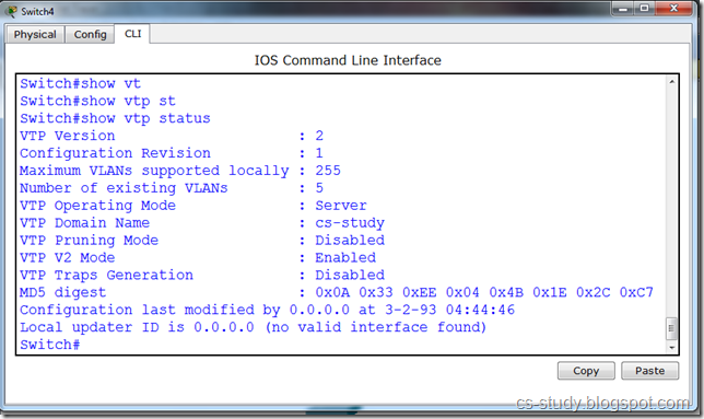
Let us see vtp status by applying the command “show vtp status”.
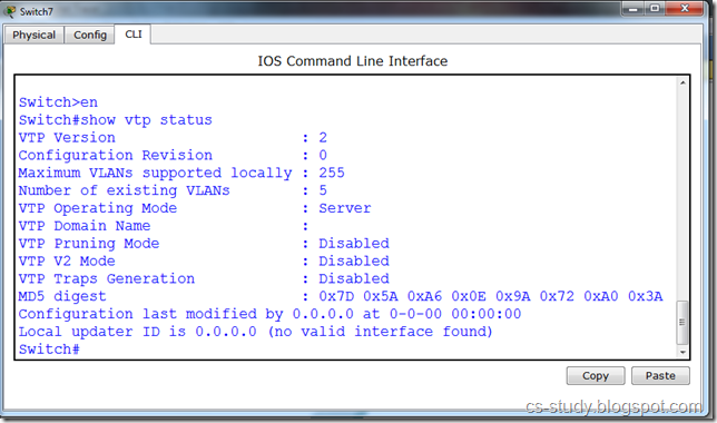
 forall
Let us set domain name. In VTP there should be only one domain name through out to synchronize between all the switches.
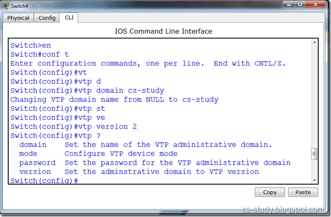
 2
Domain name is set.
3
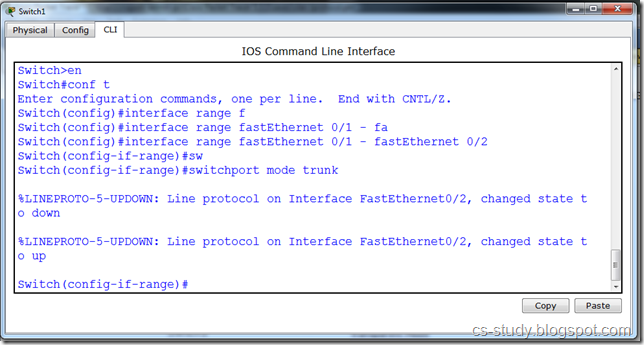
In order for changes made in one switch to take place in other switches as well. we will have to trunk the interfaces. Only those interfaces that are connected.
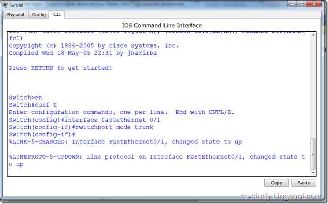
88
Or we can select a range of interfaces and trunk them.
 99
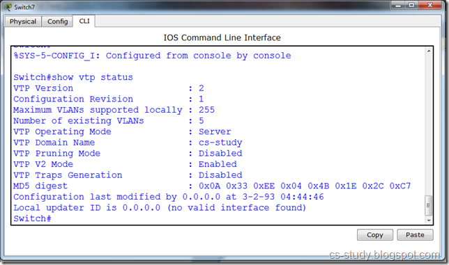
Now, when we check the status on other switches we can see that the domain name has been set on all the other switches as well.
 aftall
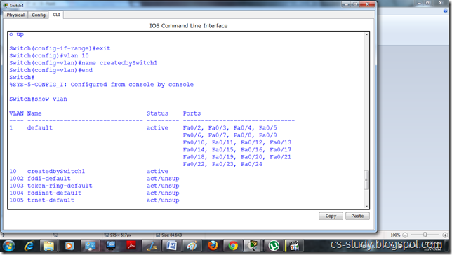
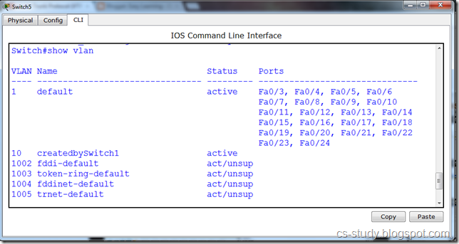
Let us create VLAN.
 4
This vlan is shown in other switch due to the trunking .
 5
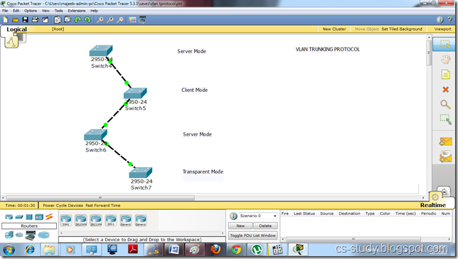
Now, there are three modes in a vtp.
i. Server
ii. Client
iii. Transparent
We are going to apply all three modes on different switches. We can create vlan in server mode, only use them in client mode. But the changes made in transparent mode are independent and does not have affect on other modes.
jj

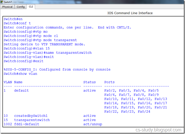
Let us turn the switch 7 to transparent mode and create a vlan in it.
 6
The vlan created in transparent mode is not visible in the other modes.
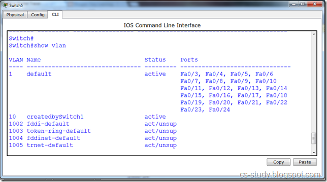
 7
If we change the mode of vtp from server to client , we are unable to create vlan now in the client mode as shown in the message below.
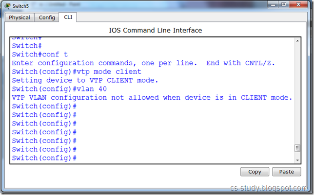
 8

November 6, 2012

Spanning Tree Protocol on Packet Tracer

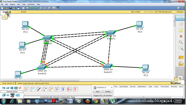
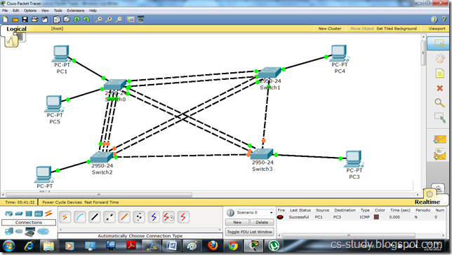
Let us apply STP on packet tracer. Let us develop a basic topology like the one in the following diagram.
y
As we can see in the above diagram that some light are green while others are orange. Y is it so ? We will see that in a moment. Let us try to communicate between two Hosts. Assign IP addresses to all hosts
uu
As we can see in the figure below, the communication is successful. It is due to the spanning tree protocol applied on the switch by default. It provides us with the loop free environment. It calculates the cost of each path and provides us with the one that has the minimum cost. That is the reason that some links are up while others are down with the orange light.
uiu
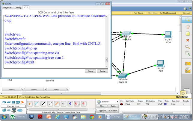
So let us see what happens if we remove the spanning tree protocol from this topology.
fff
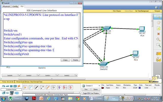
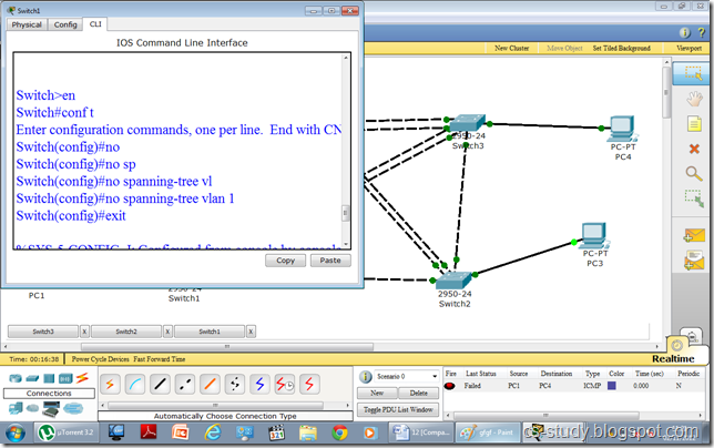
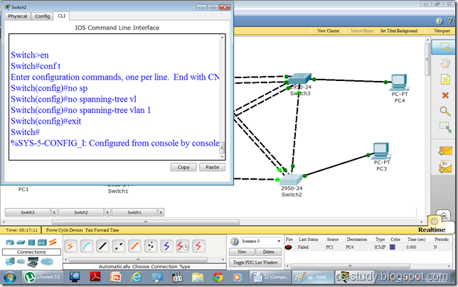
We will remove STP from all the switches one by one.
gfgf

gg
tt
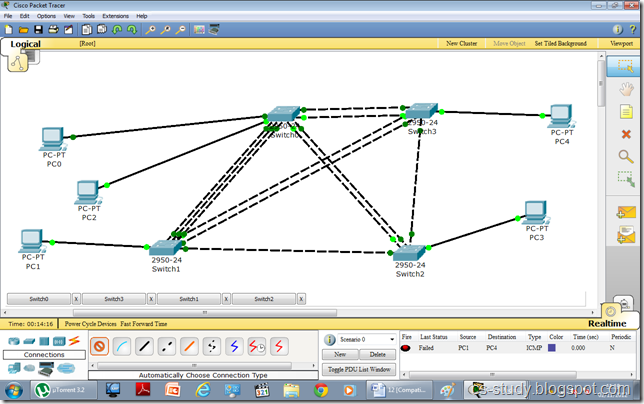
After removing STP, we have observed by the following diagram, a couple of changes. i.e. all the lights are green. In fact, some are dark green. Some lights are blinking, while some are not. This is due to fact that as there is no protocol to decide that which path to choose as we have removed STP.
d
Now that if we try to communicate between any hosts it will fail and communication is disabled.
lmklkjlk

VLAN on Packet Tracer

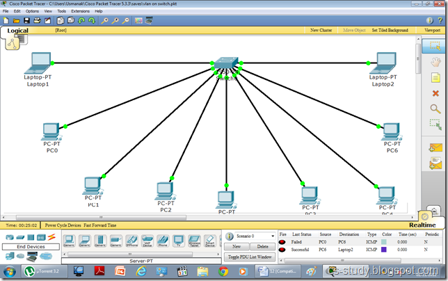
In this tutorial, we are going to apply VLAN on packet tracer. Let us create a topology with one switch and multiple hosts like in the figure below.
1
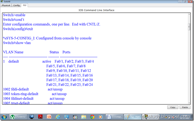
if we go to the switch and enter the command “show vlan ”. It shows the following. 
 afadsfadsf
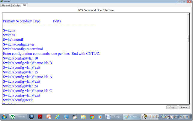
As we can see in the figure above all the interfaces are being displayed and they are all the part of the default vlan 1. Now let us apply vlans on the switch. We are going to create three vlans as follows.
 dsgs
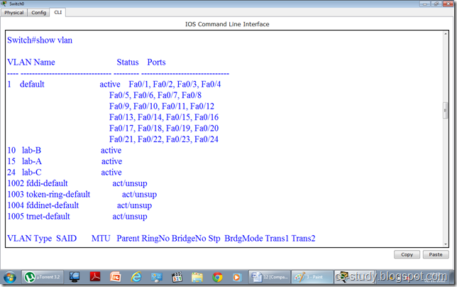
Now, that we have created the vlans. Lets see if they are visible to us.
ds
In the above figure, vlans are visible. Now, we are going to assign interfaces to vlans. They are two ways to do this.
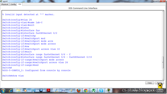
i. We can select an interface and assign that interface to a specific vlan
ii. We can select multiple interfaces (range of interfaces) at once and assign those interfaces to vlan.
In the figure below, we have done both of these.

yyy
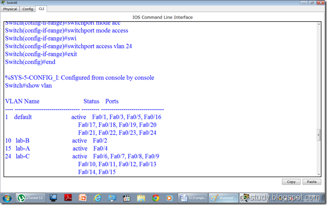
Now, when we write “show vlan “ command and observe it. We will realize that interfaces have been assigned to desired vlans respectively.
 ggggggggg
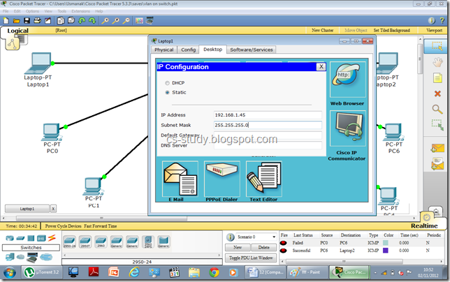
Let us assign IP addresses to PCs. Open the PC.
 fff
Assign IP address.
 kljljk
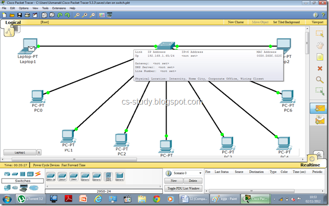
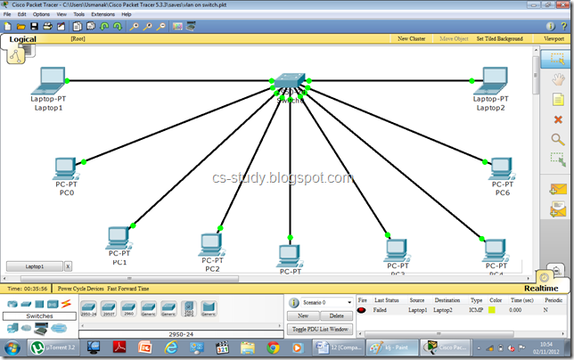
After assigning IP addresses, when we try to communicate between two PCs belonging to two different vlans, it will fail. Thus, we have achieved our purpose.
 klj
The message sending failure status can be seen in the bottom right corner.
 uu

October 28, 2012

Introduction to Packet Tracer


Packet Tracer is a protocol simulator developed at Cisco Systems. Packet Tracer (PT) is a powerful and dynamic tool that displays the various protocols used in networking, in either Real Time or Simulation mode. This includes layer 2 protocols such as Ethernet and PPP, layer 3 protocols such as IP, ICMP, and ARP, and layer 4 protocols such as TCP and UDP. Routing protocols can also be traced. Packet Tracer is a supplement to and not a replacement for experience with real equipment. Students are encouraged to compare the results obtained from Packet Tracer network models with the behavior of real equipment.

Creating a New Topology in Packet Tracer
Start Packet Tracer

clip_image002

Choosing Devices and Connections
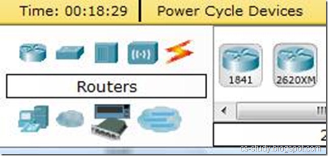
We will begin building our network topology by selecting devices and the media in which to connect them. Several types of devices and network connections can be used. For this lab we will keep it simple by using End Devices, Switches, Hubs, and Connections.
Single click on each group of devices and connections to display the various choices. When we select a device in the left panel, in the right panel we see all the listed devices of that type.


clip_image005
clip_image008


Single click on the End Devices.
clip_image017[1]

Single click on the Generic host.

clip_image017[2]

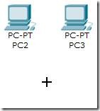
Move the cursor into topology area. You will notice it turns into a plus “+” sign.
clip_image026

Single click in the topology area and it copies the device.

 
clip_image028 clip_image030


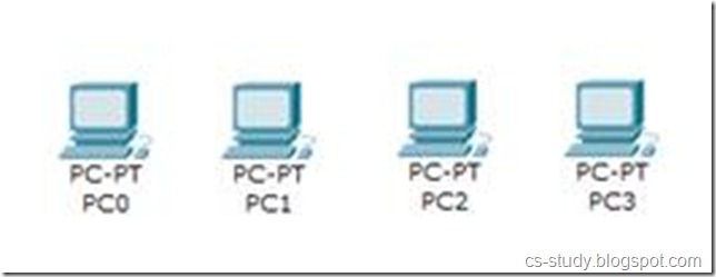
Add three more hosts.
clip_image032

Adding a Hub

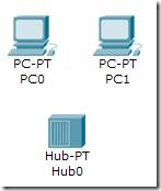
Select a hub, by clicking once on Hubs and once on a Generic hub.

 
clip_image011[1] clip_image035 clip_image037


Add the hub by moving the plus sign “+” below PC0 and PC1 and click once.
clip_image039 clip_image041


Connect PC0 to Hub0 by first choosing Connections.

clip_image015[1]

Click once on the Copper Straight-through cable.

clip_image043

Perform the following steps to connect PC0 to Hub0:
  1. Click once on PC0
  2. Choose FastEthernet
  3. Drag the cursor to Hub0
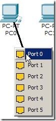
  4. Click once on Hub0 and choose Port 0
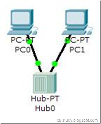
  5. Notice the green link lights on both the PC0 Ethernet NIC and the Hub0 Port 0 showing that the link is active.
1 2 3 4 5
clip_image045 clip_image047 clip_image049 clip_image051 clip_image053

Repeat the steps above for PC1 connecting it to Port 1 on Hub0. (The actual hub port you choose does not matter.
clip_image055

Adding a Switch

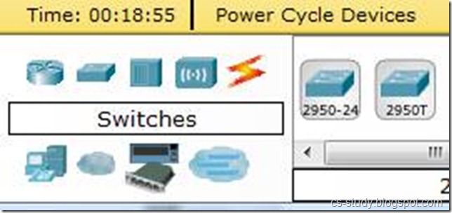
Select a switch, by clicking once on Switches and once on a 2950-24 switch.

 
clip_image008[1] clip_image058 clip_image060


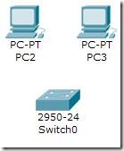
Add the switch by moving the plus sign “+” below PC2 and PC3 and click once.

 
clip_image062 clip_image064


Connect PC2 to Hub0 by first choosing Connections.

clip_image015[2]

Click once on the Copper Straight-through cable

clip_image043[1]

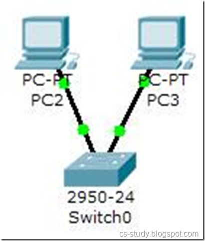
Perform the following steps to connect PC2 to Switch0:
  1. Click once on PC2
  2. Choose FastEthernet
  3. Drag the cursor to Switch0
  4. Click once on Switch0 and choose FastEthernet0/1
  5. Notice the green link lights on PC2 Ethernet NIC and amber light Switch0 FastEthernet0/1 port. The switch port is temporarily not forwarding frames, while it goes through the stages for the Spanning Tree Protocol (STP) process.
  6. After a about 30 seconds the amber light will change to green indicating that the port has entered the forwarding stage. Frames can now forwarded out the switch port.
1 2 3 4 5 6
clip_image066 clip_image068 clip_image070 clip_image072 clip_image074 clip_image076

Repeat the steps above for PC3 connecting it to Port 3 on Switch0 on port FastEtherent0/2. (The actual switch port you choose does not matter.)
clip_image078

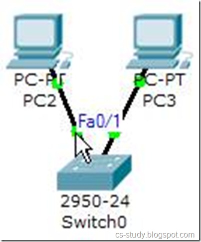
Move the cursor over the link light to view the port number. Fa means FastEthernet, 100 Mbps Ethernet.
clip_image080

After you successfully create the topology like here,

Be sure you are in Realtime mode.
clip_image108
Select the Add Simple PDU tool used to ping devices.
clip_image110

Click once on PC0, then once on PC3.
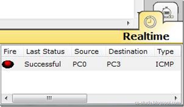
The PDU Last Status should show as Successful.
clip_image118

For a detailed successful topology creation and traffic flow, click here.


C program to Read From a File

#include <stdio.h> #include <stdlib.h> void main() {     FILE *fptr;     char filename[15];     char ch;   ...